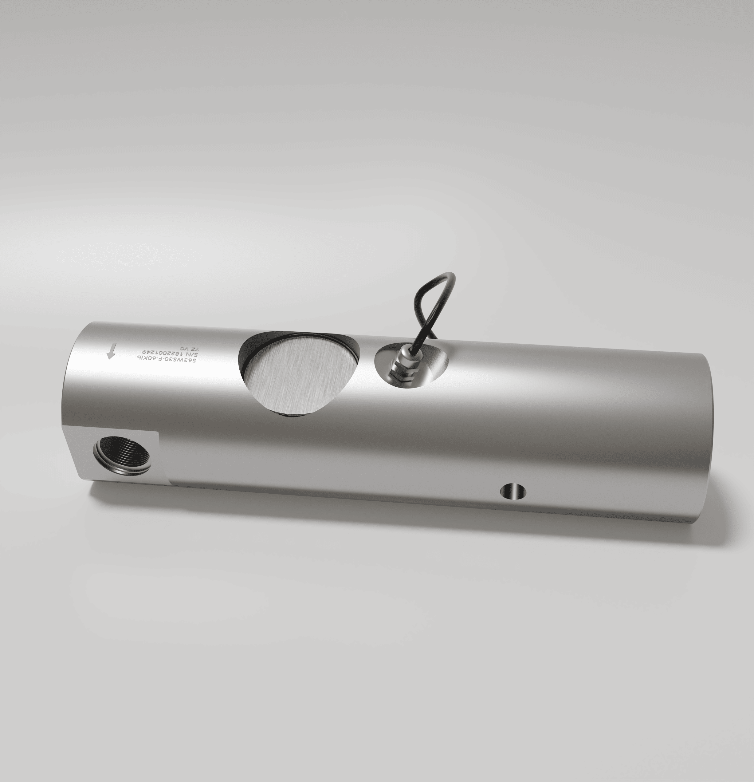
Load cells and force transducers are essential devices in weighing or measurement applications. There are no clear definitions of load cell and force transducer, but they are all sensors; usually load cell measures weight, while force transducer measures force or torque.
They are used in variety of industries such as packaging, transportation, food, farming, agriculture, construction, medical, high tech, test and measurement, and many others.
The major components of any load cell or force transducer are:
- Sensor Element, and
- Sensing electronics
Sensor Element:
The Sensor Element in a load cell or force transducer, often called “spring element”, is a precisely machined piece of metal commonly made from high strength alloy steel, or stainless steel with heat treatment, or high strength aluminum alloy.
The sensor element is made in such a way that if a load is applied to it in a certain direction and orientation, it will develop strain that is proportional to the load that is being applied. A load cell’s accuracy is highly dependent on the sensor element design and material, as well as workmanship.
Sensor Elements come in different shapes and sizes that correspond to the relevant application and load rating. Anyload provides variety of load cells as follows:
- Single Ended Shear Beam
- Double Ended Shear Beam
- S-Beam or S-Type
- Single Point
- Canister and Disk
- Planar
- Load Pins
- Load Buttons
- Tension Links
- Wire Rope
- Torque
Sensing Electronics:
The key part of sensing electronics for a load cell is the strain gauge. The strain gauge, as the name implies, can measure the strain on a piece of metal when is it bonded to it.
A strain gauge is a thin precision resistor component that changes its resistance value when it is under tension or compression.
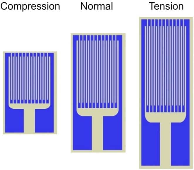
Figure 1: Strain Gauges in Compression, Normal, and Tension (change of shape is exaggerated).
To turn this change in resistance into a usable voltage output, four (or groups of four) strain gauges are attached to a sensor element in a wheat stone bridge arrangement.
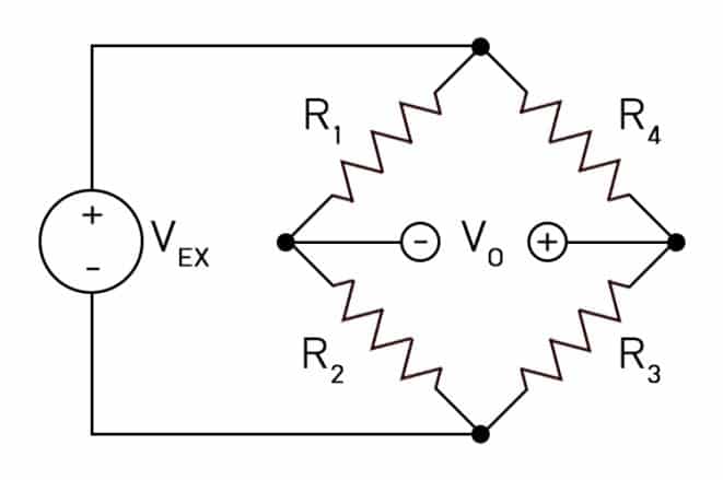
Figure 2: Strain gauge wiring diagram
The strain gauges are bonded to the sensor element in such a way that when a load is applied to the load cell, R1 and R3 will be under compression and R2 and R4 will be under tension.
How Does It Work?
To show how a load cell actually works, we will demonstrate using a single point load cell. The sensor element of a single point load cell will look similar to this illustration:
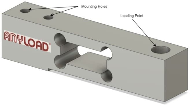
Figure 3: Single Point Load Cell Model
When a load is exerted on the load cell or force transducer at the loading point, the sensor element will produce strain according to the following simulation (refer to Figure 4). The change in shape of the sensor element is exaggerated for illustration purposes. The actual deflection of most load cells or force transducers is at most about 0.1 mm to 1 mm at full scale.
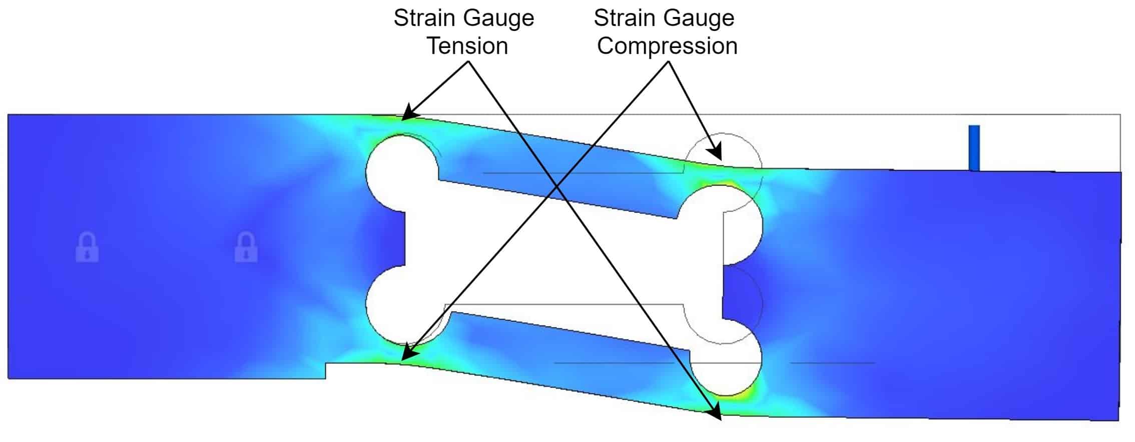
Figure 4: Single point load cell under load
In most cases, strain gauges are bonded to the sensor element at the locations where most strain will occur.
When the load cell or force transducer is in unloaded and normal condition, all the strain gauge resistance values are equal or close to equal and the voltage output of the wheat stone bridge is zero or close to zero.
When a load is applied to the sensor, the strain gauges are under compression or tension according to the schematic below:
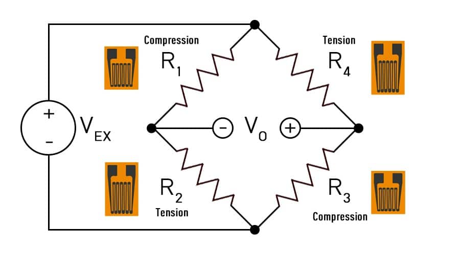
Figure 5: Strain Gauge wiring under load
In this condition, the strain gauges under compression have lower resistance and the ones under tension have higher resistance. This change in resistance will cause the voltage output to deviate from zero or close to zero by an amount that is proportional to the load applied.
Milli-Volt per Volt Output
A sensor’s output voltage with respect to the excitation or supply voltage is presented in mV/V in the specification sheet of the load cell or transducer. This value is stated for the full scale output of a load cell and commonly they are 1, 2, 3, 4 mV/V, or other numbers lower or in between.
The term “full scale output” means the voltage output of a load cell when the load cell is at full rated mechanical load.
For example, for a load cell or force transducer with 2 mV/V full-scale output, it means if the excitation voltage is 10 VDC, then at full scale the output voltage will be 20 mV according the following equation:

Load Cell or Force Transducer Compensation
Ideally a load cell with a simple wheat stone bridge circuit has an output of zero when it is unloaded. However, in reality, several resistive components have to be added to the wheat stone bridge circuit to minimize the temperature change effects and achieve zero balance in unloaded condition. A real example of a wheat stone bridge in a load cell will look similar to the following schematic:
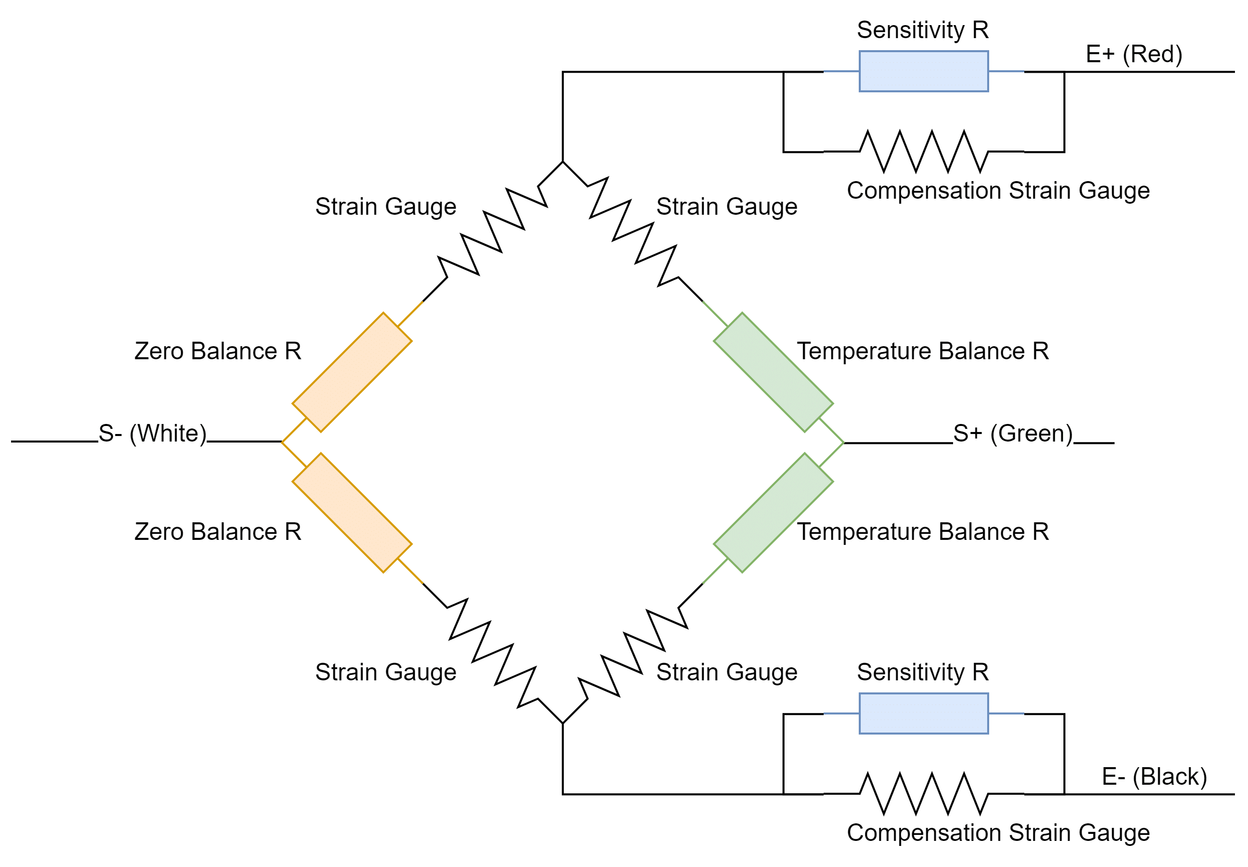
Figure 6: Example of wheat stone bridge on a load cell
There are different resistive components other than the four main strain gauges that make up a wheat stone bridge circuit. They are
- Zero balance compensation
- Temperature compensation on zero
- Sensitivity compensation
- Temperature compensation on sensitivity
Zero Balance Compensation
Since not all strain gauges are of exactly equal values and their value might change by a small amount after the bonding process to the sensor element, the zero balance resistive components will help to counter this change or difference. The goal of zero balance is to make all strain gauges bonded to a sensor element almost equal in value.
Temperature Compensation on Zero
The sensor element, as well as strain gauges will naturally expand and contract depending of the environment temperature. This can lead to false load value reading in different temperatures.
The temperature compensation component is a temperature dependant resistor that will counter the resistance changes of the main strain gauges.
Sensitivity Compensation
The sensitivity compensation components will help adjust the load cell sensitivity to a standard value of 1, 2, 3, 4 mV/V or other numbers lower or in between, full scale output within a certain tolerance range.
Temperature Compensation on Sensitivity
The sensor element, strain gauges, elastic modulus of the sensor element, will naturally change depending of the environment temperature during receiving the loading or force. This can lead to incorrect load or force value reading in different temperatures.
The temperature compensation component is a temperature dependant resistor that will counter the incorrect reading in different temperature.

